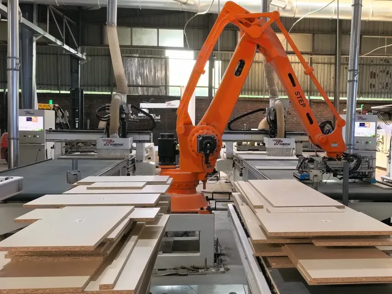
Robotic Panel Loading & Unloading | Automated Feeding System
Robotic material handling for custom furniture plants: sheet loading at the beam saw or nesting router, part unloading and stacking after cutting, infeed robots on the edge banding line, and order-based sorting. Interfaces with beam saws, nesting machines, edge banders and six-sided drills to remove manual panel handling, stabilise cycle time and reduce surface damage.
Key Features
Applications
Overview
Robotic panel handling takes the lifting and moving of boards and parts out of the equation. In a custom furniture plant the material itself is rarely the expensive part; what limits output and causes damage is the repeated lifting, turning, stacking and moving of panels. A stack of chipboard weighs tens of kilograms, it is handled hundreds of times a day, and when the people who do it cannot be found or retained, the machines end up waiting for material. A vacuum-cup robot performs those moves instead — loading, unloading and transferring between the cutting, edge banding, drilling and sorting stations — so the machining time of the host machine is no longer interrupted by handling.
It is configured around the machines and the floor you already have rather than sold as a fixed model: one robot can serve a single machine, or stand between two machines and transfer parts between them. Gripper, reach and program are sized to the panel size, weight and the loading pattern required. That is why this page carries no specification table — the bill of materials follows the actual duty.
Typical Applications
Raw sheet loading at the cutting station
The robot takes full sheets of chipboard, MDF or plywood one at a time from a magazine, rack or feed table and presents them to the CNC beam saw or nesting machine. No operator stands at the saw table lifting and aligning boards, the feeding rhythm follows the cutting cycle, and a change of board format is a program call rather than a re-setting.
Part unloading after cutting
After the cut, the robot lifts the parts and offcuts off the table, stacks them in cutting sequence, layers them by order or by cabinet, and moves the parts that need further work to the buffer position of the next station. Offloading is a common bottleneck in cutting capacity: the machine may cut quickly, but if a person cannot keep up, parts pile on the table and the cycle stalls. A robot works continuously, so the saw never waits for the offloader.
Infeed on the edge banding line
Edge banding deals with many small parts that need both faces and edges treated. The robot separates parts one by one from a trolley or buffer and feeds them to the edge bander at its infeed speed; on the outfeed side it takes the parts off, turns them where a second edge type is required and returns them through the machine. With the line fed by robot, the edge bander runs to its own cycle, and edges and faces stop being knocked against each other during handling.
Sorting by order
After cutting or drilling, the parts of one order arrive mixed together and have to be split by cabinet, room or next operation. The robot identifies each part from the machining data and places it into the right trolley or at the right station, replacing manual label checking. The value here is the error rate: a part mis-sorted into the wrong operation costs far more to rework than the sorting step itself.
Drilling machines and inter-station transfer
Loading and unloading of six-sided drills and PTP drilling machines, and the transfer and buffering of parts between cutting, edge banding, drilling and packing, run on the same handling cell, which is what turns a group of single machines into a continuous line.
Integration With the Machines
The robot is signal-linked with the machine it serves: it does not reach for a part while machining is still running, and when a fence, light guard or safety mat is triggered, both sides stop together. Pick and place positions, the panel size range and the gripper are defined by the machine table, which is why the same concept fits beam saws, nesting machines, edge banders and six-sided drills, and can also be added behind machines you already own.
The control system receives the upstream machining data and uses it to decide which part to move next and where it goes, so the handling sequence stays aligned with the order rather than simply shuttling panels back and forth.
What We Need to Specify the System
The layout and the quotation follow from these inputs; we fill in the rest from experience:
- Plant layout and the floor area available for the handling cell
- The machine to be served (model, table size, infeed and outfeed direction)
- Panel size and thickness range, weight per part and per stack
- Which operations should be automated: raw sheet loading, offloading after cutting, edge bander infeed, sorting, or transfer between stations
- Whether turning, return pass or stacking by order is required, plus shift pattern and target output
Note: This page describes how robotic loading and unloading is applied in custom furniture production and carries no fixed technical data; gripper type, reach and cycle time are defined by the duty.
Request a Quote
Only the starred fields are required. We'll get back to you within 24 hours.
Need Help Choosing?
Our engineers can help you select the right machine for your production needs.
Chat on WhatsApp